A computer-assisted pipeline for intra-operative CMFS reconstruction
A CAD-CAM pipeline for facial and skeletal reconstruction
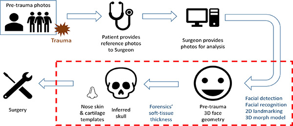
In CMF reconstruction, the goal is to recreate the pre-traumatic appearance of the individual. Using pre-trauma 2D photographs, a pipeline of facial detection (finding faces in images), facial recognition (finding the same person’s face), facial landmarking (locating points of interest on the face) and face morph modelling (generating 3D face guided by landmarks) can be used to create a pre-trauma 3D face geometry. A 'reverse-engineering’ of a forensics soft tissue model can then be used to determine the underlying skull shape from the 3D facial surface topography.
Click to view a plain-text version of infographic
- Pre-trauma photos
- Patient provides reference photos to surgeon
- Surgeon provides photos for analysis
- Facial detection, facial recognition, 2D landmarking, 3D morph model
- Pre-trauma 3D face geometry
- Forensics' soft-tissue thickness
- Inferred skull
- Nose skin & cartilage templates
- Surgery
The pipeline which goes from photo to face model to underlying craniomaxillofacial skeleton (CMFS) must consider age, sex, BMI, ethnicity, and facial expression. Application for this is in both form and function considering re-establishment of appearance, structure and facial reanimation.
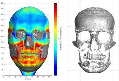
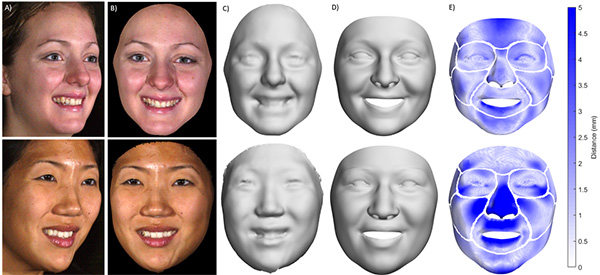 A) A three-quarter side view 2D photos, B) Front view 2D photos, C) Corresponding 3D face shape surfaces, D) Basel face model 2017 3D facial estimate for the front 2D photos, E) Regional per-vertex Euclidean distance error between the estimate and the true scans (0-5 mm), F) Soft tissue depth map, G) Inferred skull.
An application of the CAD-CAM pipeline is shown in nasal reconstruction following trauma or tumour resection. A forehead flap graft can be preoperatively planned based on a 3D facial reconstruction. Flattening software transforms the 3D shape into a physical template for the graft to direct intraoperative cutting of a skin flap.
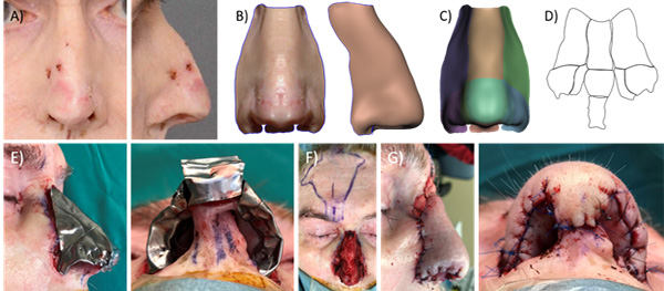 A) Patient photos with cancerous regions, B) Mirrored 3D scan with sculpted nostril, C) Nose labelled with aesthetic subunits, D) Flattened nose template with subunit boundaries (not to scale). E) Template traced in foil and test-fit into the defect, F) Template traced on the forehead, G) Forehead flap transferred and sutured.
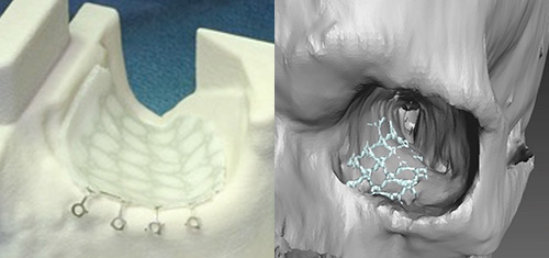
Patient-specific CMFS implants made in the operating room
Calavera Surgical Design (a Sunnybrook start up company) has a process which creates unique patient-specific implants from standard commercial meshes that can be modified in the OR – enabling intraoperative sizing of the implants based on the actual resection. We have developed a new image analysis pipeline, including our deblurring algorithm, which has been integrated into Calavera’s clinical workflow, to reduce time and manual intervention in creating the designs.